Titan ReloadingMidSouth Shooters SupplyWidenersInline Fabrication
Reloading EverythingRotoMetals2Load DataLee Precision
Snyders Jerky Repackbox
Page 1 of 2 12 LastLast
Results 1 to 20 of 24

Thread: I need help with my PID controller

  1. #1
    Boolit Buddy
    Join Date
    Aug 2012
    Location
    Biloxi, MS
    Posts
    239

    I need help with my PID controller

    Quote Originally Posted by Bodine View Post
    http://castboolits.gunloads.com/show...ller-Schematic


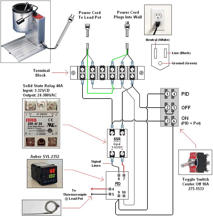
    I am having issues with my PID setup. I wired it like in this diagram above, terminal strip and all with a couple of exceptions. I did not use the first indicator light by the switch in the diagram, nor did I install the 2nd fuse prior to the lead pot. The temperature reads fine from my thermocouple, but I think I may have a wiring issue between the PID and the lead pot. The indicator light that is supposed to light up when the pot is on stays on really dim and flickers, but the plug for the lead pot doesn't work. I will try to get some voltmeter readings this morning when I get home from work. Also, I have read enough threads about the PID's to make my head swim, but I haven't seen mention of the settings for the controller. I read the auberins manual on my PID and I am so confused what I'm supposed to setup or change. I THINK I made the change for the set temp to be 100 to check and see if the indicator light went off when it reached that temp in hot water, but the light never switched off. Also, I looked at the following diagram and it appears the connections on the upper part of the SSR are reversed. could this be the issue?


    I am using the following
    1/32 PID http://www.auberins.com/index.php?ma...products_id=14

    25a SSR http://www.auberins.com/index.php?ma...&products_id=9
    Last edited by n10sivern; 02-22-2014 at 03:23 AM.

  2. #2
    Boolit Master dikman's Avatar
    Join Date
    May 2013
    Location
    Sth Oz - A Land Downunder
    Posts
    2,087
    I'm not sure what you mean by the upper part of the SSR? If you mean the AC connections, it doesn't matter which way round they go. Also, that SSR has an LED in it. If the SSR has power going to it from the PID then the LED will be on.

    Have you selected the correct output (outy) in the PID? The SSR output has to be enabled, should be set to 2 if I'm reading the instructions right (my XMT PID didn't have any output at first, turns out the default factory setting was SSR off!!).

    Have you changed any of the settings in the PID?

  3. #3
    Boolit Buddy
    Join Date
    Aug 2012
    Location
    Biloxi, MS
    Posts
    239
    no i didn't change anything on the PID other than setting a target temp. looking at the manual linked below, 2nd page, note 2 on rt side, I need to set the output as 2? http://auberins.com/images/Manual/SY...tion%201.0.pdf

    also, I have been racking my brain over this and looking over the wiring schematics over and over and it finally hit me. I realized I did a stupid thing. My hot wire from the SSR, I soldered it to the indicator light and then from the light to the plug in. I am pretty sure there is a resistor in the indicator light so it will be lowering the amperage to the plugin. I need to solder a wire from the SSR to the plug in and tap the indicator light in as parallel, because curently it is in series.

    By upper part of the SSR, I meant looking at the schematic. The SSR lines are labeled 1, 2, 3, 4 on it with 3 and 4 (bottom of the SSR) being the power to the SSR from the PID. On the initial schematic (the pdf link in the quote) the SSR is labeled L1, T1, A2-, A1+. T1 (top right corner of the SSR) is the line to the lead pot. In the picture above, the line to the lead pot is the top left corner. In the manual for the PID, it shows #2 (top right) to the lead pot.

  4. #4
    Boolit Buddy
    Lee W's Avatar
    Join Date
    Mar 2005
    Location
    Upstate NY
    Posts
    290
    It seems the diagram above does not have the same pin out as the controller you are using. 6-7 for the thermocouple and 9-10 for the SSR.
    You will need to set the input to the correct thermocouple type and output to control the SSR. Page 2 describes these changes.
    The SSR output is just 8 volts. If the indicator light drops the voltage under 4.5 volts, the SSR will not work.

  5. #5
    Boolit Master dikman's Avatar
    Join Date
    May 2013
    Location
    Sth Oz - A Land Downunder
    Posts
    2,087
    The actual designations on the SSR don't matter that much. The AC voltage is clearly labelled, as is the control connections from the PID, these will always have a +ve and -ve label. As I said, the AC doesn't matter which way they're connected, but the +ve and -ve must match the same connections on the PID.

    As for the lights, I didn't bother with any on mine. When the power is on the PID lights up (!) and my Promelt has a light in its on-off switch, so when it's on I know that power is going to the pot (this should cycle on and off with the PID). I deliberately kept mine simple, with no extra lights or LED's.

    The default setting on yours is for a K probe, so that should be ok. Lee is right about the connections, did you wire it according to the manual or the diagram you listed?

  6. #6
    Boolit Buddy
    Join Date
    Aug 2012
    Location
    Biloxi, MS
    Posts
    239
    The PID is wired correctly per the manual. I questioned the wiring for the SSR. I know I have the 2 wires from the PID to the SSR correct. I don't know if I have the hot wire and the wire to the lead pot right or switched. The PID manual has a diagram with a SSR. Mine is wired that way, but I've seen other schematics that have the two wires switched on the SSR. I guess not all SSRs are made the same. I did not change any of the PID settings except the target temperature. I wired in a light as the Lee pot doesn't have one and I can't see the SSR light because it's in my enclosure. I think if I make sure my settings are correct on the PID and I rewire the light correctly it'll work.

  7. #7
    Banned
    Join Date
    Nov 2010
    Location
    Casa Grande, AZ
    Posts
    5,526
    The SSR has a positive and negative input signal. The PID has a positive and negative output for the SSR. Simply run the positive from the PID to the positive on the SSR. Run the negative from the PID to the negative on the SSR.

    Your "LOAD" on leg will go to the other side of the SSR.

    The AC voltage used to power up the PID has no polarity.

    If you have to ....remove the guts and look over and check to see if everything is correct before putting it back together.

  8. #8
    Boolit Buddy
    Join Date
    Aug 2012
    Location
    Biloxi, MS
    Posts
    239
    Quote Originally Posted by 6bg6ga View Post
    The SSR has a positive and negative input signal. The PID has a positive and negative output for the SSR. Simply run the positive from the PID to the positive on the SSR. Run the negative from the PID to the negative on the SSR.

    Your "LOAD" on leg will go to the other side of the SSR.

    The AC voltage used to power up the PID has no polarity.

    If you have to ....remove the guts and look over and check to see if everything is correct before putting it back together.
    Everything up to the SSR is wired correctly, which includes the PID. I have the input + and - wired correctly like I said in my previous post. I questioned how I know if I have the other 2 legs wired correctly. They are marked 1 and 2. One goes to hot wire and the other to the lead pot. I wired those 2 legs like pictured in the PID manual. However, I've seen those 2 leads swapped back and forth in other wiring schematics. I am just wondering how I know which is right and if it matters.

  9. #9
    Boolit Grand Master popper's Avatar
    Join Date
    Jun 2011
    Posts
    10,594
    Wire from pin 3 of switch should go to other SSR terminal and eliminate the wire from SSR to terminal board. The SSR is a series switch connection. They way you have it wired, the SSR does nothing.
    Whatever!

  10. #10
    Boolit Grand Master jmorris's Avatar
    Join Date
    Aug 2007
    Posts
    5,291
    Also, I have read enough threads about the PID's to make my head swim, but I haven't seen mention of the settings for the controller.
    I have a number of them from different manufactures and have spend days recording parameter changes and results when used on outdoor wood burning cookers. Then one day I was given another box of them and they had an "auto learn" function that could pretty much figure out what I had in a much shorter time.

    In short if yours has an auto mode give it a try first. I could go pull up the parameters on mine but they might not help much as my pot is 3/8" thick steel, uses a 3500w element and holds over 60lbs of lead. A lot different than a Lee pot.

  11. #11
    Boolit Buddy
    Join Date
    Aug 2012
    Location
    Biloxi, MS
    Posts
    239
    Quote Originally Posted by popper View Post
    Wire from pin 3 of switch should go to other SSR terminal and eliminate the wire from SSR to terminal board. The SSR is a series switch connection. They way you have it wired, the SSR does nothing.
    I don't understand what switch you are talking about. I only have 1 switch and it is the on/off at the power in

  12. #12
    Boolit Buddy
    Join Date
    Aug 2012
    Location
    Biloxi, MS
    Posts
    239
    I re-wired the indicator light. I attached a crude picture of how mine is wired, that way there is no confusion with the schematics of others that I posted initially. I did not set the PID to auto tune. I plugged everything in, the thermometer read 73 for my house temp. I set the target temp at 90. I plugged in a light to where the lead pot would plug in that way I could see if it was working. The light pulsed on and off every second. I put the thermocouple into hot water and the pulsing light slowed until it went above the target temp and then the light stayed off. I pulled the thermocouple out of the hot water and once it started cooling toward room air temp the pulsing light returned. Is this correct function of everything? The light on the SSR is turning on and off with the light that I have plugged in. If there was a much greater temperature difference between the ambient air and the target temp would it just stay on until it got closer or would it pulse on/off like it was?


  13. #13
    Boolit Bub
    Join Date
    May 2013
    Posts
    40
    The switch bypasses the ssr in one of the positions. It is a "on - off - on" switch. Not sure why you need this. I only put an "overtemp alarm" lamp in mine. There is a light on the front of the pid that tells if it is cycling or not.

  14. #14
    Boolit Buddy
    Join Date
    Aug 2012
    Location
    Biloxi, MS
    Posts
    239
    Quote Originally Posted by double bogey View Post
    The switch bypasses the ssr in one of the positions. It is a "on - off - on" switch. Not sure why you need this. I only put an "overtemp alarm" lamp in mine. There is a light on the front of the pid that tells if it is cycling or not.
    I believe you are looking at somebody else's schematic that I posted as an example of how they wired the SSR. I don't have a 3 position switch. I only have an on/off switch at the power source. As far as the light on the PID, I realize it is there, it's just really small. If I realize I don't need it or use it I may just rewire the light as an over temp alarm light. I just figured I could easily see the numbers and know if the temp was too high where the light for the working pot is really small.

  15. #15
    Boolit Grand Master popper's Avatar
    Join Date
    Jun 2011
    Posts
    10,594
    You got it right, it works. Hope the other guy gets his to work. My pot buzzes so I don't need an indicator on it. Mine doesn't have a switch, just unplug it. I also use it on my oven for PCing.
    Whatever!

  16. #16
    Boolit Master

    Mike W1's Avatar
    Join Date
    Nov 2008
    Location
    Rural Sumner, IA
    Posts
    1,317
    Going to do a little studying this morning but I'm thinking if you're wired like in post #1 here it's not wired right. I have a SYL-2352 which is a 1/16 PID and your link takes me to a SYL-1512A2 which does not wire up the same. For example on a 2352 the TC goes to terminals 4 & 5 and on a 1512 it looks like they go to terminals 6 & 7. Wife is fixing breakfast and I'd better not be tardy but will do a little more looking later.

    Too bad they banned Frozone, he probably figure it out in a minute!
    Mike

    Benefactor Member NRA
    Life Member Iowa Firearms Coalition
    US Army Vet

    There are two ways to conquer and enslave a nation.
    One is by the sword. The other is by debt.”
    John Adams 1826

  17. #17
    Boolit Master

    Mike W1's Avatar
    Join Date
    Nov 2008
    Location
    Rural Sumner, IA
    Posts
    1,317
    Quote Originally Posted by n10sivern View Post
    I re-wired the indicator light. I attached a crude picture of how mine is wired, that way there is no confusion with the schematics of others that I posted initially. I did not set the PID to auto tune. I plugged everything in, the thermometer read 73 for my house temp. I set the target temp at 90. I plugged in a light to where the lead pot would plug in that way I could see if it was working. The light pulsed on and off every second. I put the thermocouple into hot water and the pulsing light slowed until it went above the target temp and then the light stayed off. I pulled the thermocouple out of the hot water and once it started cooling toward room air temp the pulsing light returned. Is this correct function of everything? The light on the SSR is turning on and off with the light that I have plugged in. If there was a much greater temperature difference between the ambient air and the target temp would it just stay on until it got closer or would it pulse on/off like it was?

    Looks like it's wired right to me. I had an extra neon indicator and wired one similarly just so it's more visible. With no more load than a light bulb and the TC not actually doing something I think you're seeing normal indications. Plug your pot into the unit with the TC in the lead and I suspect you'll find it woring for you. Set your temperature and alarm settings and then run AT and bet it'll work fine.
    Mike

    Benefactor Member NRA
    Life Member Iowa Firearms Coalition
    US Army Vet

    There are two ways to conquer and enslave a nation.
    One is by the sword. The other is by debt.”
    John Adams 1826

  18. #18
    Boolit Grand Master jmorris's Avatar
    Join Date
    Aug 2007
    Posts
    5,291
    If there was a much greater temperature difference between the ambient air and the target temp would it just stay on until it got closer or would it pulse on/off like it was?
    That depends on the values stored in the controller.

    The settings would be quite different for the controller to control your SSR and relate that to the temp change at the thermocouple than they would be controlling a solenoid feeding cold water inline with hot water to maintain a specific output temp.

    Write down the values in the controller now and then let it auto tune and note the difference.

  19. #19
    Boolit Master el34's Avatar
    Join Date
    May 2013
    Location
    N Texas
    Posts
    1,190
    Is the neon light the one that glows dimly when it's supposed to be off? If so, it's leakage current through the SSR. An incredibly small amount of current is all a neon requires. To fix mine I put a resistor in parallel with the neon to swamp the leakage current.

    From a PM to a member many months ago-

    What worked on mine was a 25K 1 watt resistor across the output to the pot. I didn't have such a resistor handy so I took four 100k 1/4watt resistors and twisted them together in parallel (side by side, not end to end). Math-wise, the 25k final resistance in parallel is 100k divided by 4, but power-wise the 1 watt result is from 1/4 watt multiplied by 4.

    Using these resistors is good because Radio Shack has 100k 1/4W but not many 1 watt'ers.

    On mine it took the effect of the leakage down to 25VAC, way below the 70-80V (approx) required to light a neon.

    When the SSR is ON, all 110V will of course be across the 25k resistor. It will dissipate 0.48 watts, a comfortable margin under the 1 watt capability.


    If the pot is plugged it will kill the leakage and the neon will be off when it's supposed to be. But you said your outlet to the pot doesn't work yet.
    "The urge to save humanity is almost always a false front for the urge to rule." --H. L. Menchen

  20. #20
    Boolit Master dikman's Avatar
    Join Date
    May 2013
    Location
    Sth Oz - A Land Downunder
    Posts
    2,087
    n10sivern, from your description of what the lamp's doing it sounds like it's working. As soon as the probe reaches the set temp. the PID turns off the SSR, which turns off the light. As 6bg and I said, it doesn't matter which terminals you connect the AC load to (either 1 or 2) either way will work.

Posting Permissions

  • You may not post new threads
  • You may not post replies
  • You may not post attachments
  • You may not edit your posts
  •  
Abbreviations used in Reloading

BP Bronze Point IMR Improved Military Rifle PTD Pointed
BR Bench Rest M Magnum RN Round Nose
BT Boat Tail PL Power-Lokt SP Soft Point
C Compressed Charge PR Primer SPCL Soft Point "Core-Lokt"
HP Hollow Point PSPCL Pointed Soft Point "Core Lokt" C.O.L. Cartridge Overall Length
PSP Pointed Soft Point Spz Spitzer Point SBT Spitzer Boat Tail
LRN Lead Round Nose LWC Lead Wad Cutter LSWC Lead Semi Wad Cutter
GC Gas Check